

CLAUDIUS84
Content Type
Profiles
Forums
Events
Posts posted by CLAUDIUS84
-
-
In Hyper Terminal the CTRL+G didn't work and the prompt didn't appear
"Ctrl + G" ?????
 Why? It is "Ctrl+z", It is n't?0
 -
Hi. Another "lucky"seagate owner here.
My hard drive have BSY error. I've been trying to connect to drive using homemade converter. When i connect to terminal i got series of unreadable characters , you can see that in screenshot.
Any ideas what's wrong? I tested my converter using loopback test and it works fine.
I used this schematic. http://sodoityourself.com/max232-serial-level-converter/
First, try to inverts the wires Tx and Rx. Also check that ground TTL is well connected.
0 -
Hi guys I have a problem I type m0,2,2,0,0,0,0,22 command in terminal and didn't get any answer from terminal I wait about 30 minutes. It still show the m0,2,2,0,0,0,0,22 command and i can't write any signs on terminal. What can I do now ?? I read I can't turn off power. Help please. Sorry for my bad english.
I got that too . Start from the beginning, including the optional command "Aviko": F712, F,, 22 and F712. (with SD15 only ).
It worked for me.
HERE:
0 -
>Happybear
Arghhhh!!! Classic.
As many times you close and open the hyperterminal, as many times you open new virtual com port.
0 -
Hi HappyBear,
I am not an expert, but I had the same problem initially - no response. It seems, and Gradius2 explains this as well on the bottom of his page, that the wires have to be inverted. I inverted them and everything worked fine.
The other problem I encountered was that the TTL board was not recognized by Windows. It seemed that the batteries were not strong enough. So I connected the adapter to the 5V output from the Power supply (red wire and black one).
Good luck,
Eddy
Eddy, thanks for your effort, but -- as I wrote in my post -- I get some output from the drive (but only in the BSY state and maybe a bit strange), so I suppose the wires are OK as like as the TTL board communicates with Windows. I spent several hours on this problem yesterday and I also tried to swap TX/RX wires but I get really no response if I do that so I belive the problem must be elsewhere -- I only can't find our where is it... :-(( Has anyone any other idea please? See the original post #787 for details...
Thanks a lot.
HappyBear
Is ground TTL well connected to PCB?
0 -
-
the ca-42 i got has 5 cables.
white
yellow
green
black
red
the only way i can type in hyperterminal is if the yellow and white wires are crossed - does this mean they are the rx/tx wires?
also crossing theblack and yellow wires brings up random characters - so is the black the ground?
i dont have a circuit tester or multimeter so cant check the outputs from the usb?
HELP!
--
MAXTOR STM3500320AS 500GB MX15 NOT SEEN IN BIOS
Hello, i have a similar.
If well the same, I think:
white=Tx
green=Rx
yellow= ground data, cable shield.
and
RED=+5V, pay attention, no connect to DD/TTL.
black=ground power
im even more confused now.
i thought;
white - tx
yellow - rx
black - ground.
but when i connect white + green it shows some random stuff also - so is green ground too?
AND when i do yellow + green I can type meaning green may be rx/tx??
can I do any damage by using wrong cable?
Disconnect from DD, connect white and green and type caracters with hyperterminal, if the caracters typed will appear on screen, that means RX and TX are well white and green.
If else, connect both yellow and green, and see.
0 -
the ca-42 i got has 5 cables.
white
yellow
green
black
red
the only way i can type in hyperterminal is if the yellow and white wires are crossed - does this mean they are the rx/tx wires?
also crossing theblack and yellow wires brings up random characters - so is the black the ground?
i dont have a circuit tester or multimeter so cant check the outputs from the usb?
HELP!
--
MAXTOR STM3500320AS 500GB MX15 NOT SEEN IN BIOS
Hello, i have a similar.
If well the same, I think:
white=Tx
green=Rx
yellow= ground data, cable shield.
and
RED=+5V, pay attention, no connect to DD/TTL.
black=ground power
0 -
Thanks to gradius2 for initiate this thread and thanks to Aviko for his explain about yura's method.
Aviko, thanks so much.
Aviko's explanations are clear and all is fine. My seagate 1 toctet is now back, and my data also...
I used only a chinese copy of CA-42, 3,50 euros!
Thanks, many thanks and thanks all.
:thumbup 0 -
This is my CA-42 imitation.
Yellow = R3
Blue = R4
Red = GND
White = ?
Orange = ?
Green = ?
I've peeled a bit of the black stuff but can't see the last three wires.
Since GND is Ground what is R3 & R4? Are these the TX & RX wires? Which is which? Do I need the other three? How do I connect to the harddisk (physically)? I already chipped off a cd-rom cable & just need to know which end goes where.
Hi
pinout Nokia ca-42 here:
http://pinouts.ru/CellularPhones-Nokia/nok...op_pinout.shtml
But beware, all the cables ca-42 are not compatible. ( pin 6 and 7 as USB or TTL logic Tx and Rx )
0 -
Hello~
HD model : ST3750330AS
Firmware : SD15
I would like to ask can I use this model of RS-232 to TTL converter?? I need to comfirm it can be used before ordering.
BTY, from the pic I not sure which pins are the TX and RX...
Hopefully someone can help me, thank you.
Hello, where can you find +7 volt and -18volt for external power supply?
And 3,3 volts seems better than 5 v for output power TTL logic. So....
0 -
Gradius2, you are a big hero for me .
I got my all files back with your bsy direct guide.
using by a usb to ttl coverter
http://re-coder.com/index_dosyalar/Page624.htm
Thank you so much...
45 $
0 -
Thanks from France,AVIKO, i am waiting after my adaptator USB/TTL. Soon, i hope.
0 -
And finally before commands:
0 -
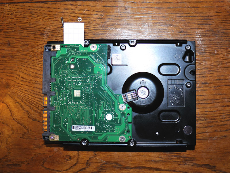
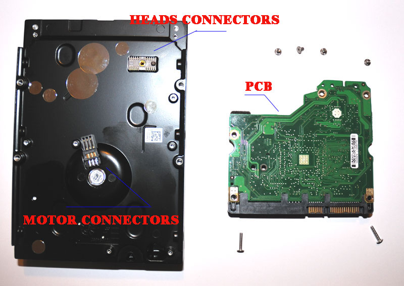
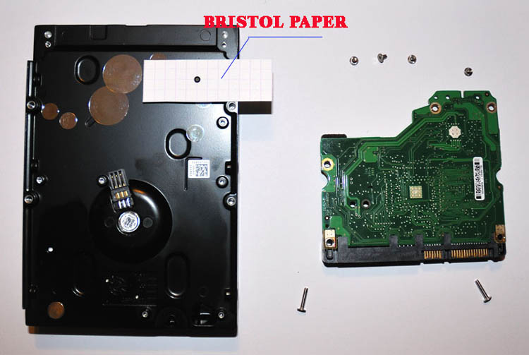
Hello Aviko,
I have some pictures to clarify to isolation to do. Right about your method? Thanks.
0
 Why? It is "Ctrl+z", It is n't?


 :thumbup

 .
.
The Solution for Seagate 7200.11 HDDs
in Hard Drive and Removable Media
Posted
Is the data ground connected to pin 2?
Try this.